

The model allowed to estimate instantaneous and cumulative fuel consumption on the considered EUDC: results are plotted in Figure 11. The red solid line represents the cumulative fuel consumption for the engine with the honeycomb substrate (“h_Giani”), which is assumed as reference to highlight the effects of open cell substrates. Therefore, in Figure 11 blue and green lines show the percentage deviation when the foam (green solid line, “f_Giani”) and Kelvin Cells substrates (blue solid line, “f_Lucci”) are used with reference to the honeycomb one (“h_Giani”).
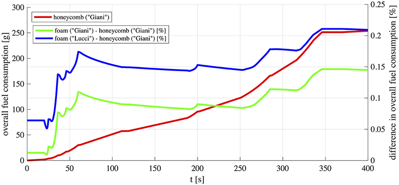 FIGURE 11. Calculated cumulative fuel consumption during the EUDC.
The analysis of the instantaneous fuel consumption ṁf shows that, within the assumed conditions, lower values are reached for the honeycomb than for both open cell foam structures. However, differences in cumulative fuel consumption between the cases is lower than 0.20%. Furthermore, among the open cell substrates, fuel consumption with real foams (“f_Giani”) is slightly lower than that with Kelvin Cells structures (“f_Lucci”).
As previously shown, pressure drop through the catalytic converter is higher for open cell structures (Figure 7) for all the analyzed cases, confirming that open cell structures are characterized by higher flow resistance. This is the main reason of higher fuel consumption for the considered open cell structures especially during accelerations. At higher engine loads and higher exhaust mass flows, the pressure drop increase in the exhaust manifold is more pronounced. It should be noted, however, that in the present study increase in fuel consumption is caused by the replacement of a honeycomb substrate with open cell foams assuming equal shape and volume. But higher mass transfer properties of open cell structures allow for more compact reactors compared to honeycomb ones, and this leads to a decrease in their flow resistance thus rebalancing the drawback in fuel consumption.
The maximum deviation observed in instantaneous fuel consumption between all the cases was 0.35%, appearing only during accelerations when higher torque is requested. During steady driving conditions at constant velocity the increased instantaneous fuel consumption due to the open cell structure substrate is lower (0.10% approximately). These variations result in an increase of only 0.20% in total injected fuel over the whole 400 s of the cycle.
Conclusions
Mathematical models represent an interesting (and often unavoidable) way to get a proper understanding of the behavior of complex systems. As a matter of fact, development of theoretical tools requires a good compromise between physical and empirical approaches to limit the CPU time.
In the paper a fast model of a catalytic converter for automotive application has been built up and integrated in a 0D “crank-angle” model of a turbocharged Diesel engine. After improving the heat exchange model for the exhaust manifold (to take account of thermal dynamics during transients), a 0D model of the catalyst has been developed to simulate related flow and thermal processes. Then the catalyst model has been coupled to an engine model to investigate the behavior of the overall system and the effects of catalyst substrate characteristics. To this extent an actual 1.6 l turbocharged Diesel engine with EGR has been simulated within an EUDC driving cycle comparing engine performance with different catalyst substrates.
The behavior of three different catalytic structures was analyzed: honeycomb, open cell foams and open Kelvin cell structures. It has been shown that, using reactors of the same volume, the increased pressure drop caused by open cell structures results in a total fuel consumption increase not higher than 0.20%. On the other side open cell structures show faster thermal transients due to their lower thermal inertial and thus are able to reach quickly light-off temperatures.
It should be noted that higher mass transfer properties of open cell structures may allow for more compact reactors compared to honeycombs. This may help to reduce the overall flow resistance of foams giving new possibilities to improve the efficiency of the after-treatment system lowering at the same time specific fuel consumption. The presented mathematical tool proved to be very effective to simulate the behavior of the comprehensive system (engine+after-treatment system) and will be used in the next future to explore exhaustively these topics.
It should be recalled that in the presented model working fluid has been considered as a mixture of 7 chemical species, i.e., N2, O2, CO2, H2O, CO, H2 NO. The number N and the type of involved pollutants depend on the specific application. In the presented model CO and one or more species representative of HC have been considered, since their oxidation reactions were assumed as the most significant in the determination of the catalyst temperature. Different after-treatment systems can be considered in the next future, e.g., three way catalysts (which represents a very interesting application for these new solutions). Modeling a three way catalyst however, is more complex since it involves the oxygen balance (gasoline engines are always near stoichiometric operation) and thus always operating under oxygen shortage. The presented approach can be used to attempt modeling a three way catalyst under real driving conditions in real-time.
Finally it should be emphasized that in the presented work the vehicle model has not yet been developed. Therefore, required input parameters (i.e., rotational speed, fuel mass flow rate, VGT and EGR driving signals) were defined through an inverse model of the vehicle (developed in Guzzella and Sciarretta, 2005). Therefore, the simpler EUDC cycle was chosen since it is a modal driving cycle, still significant enough to allow testing the effectiveness and flexibility of the proposed simulation tool. In the next step of the activity a suitable model for the vehicle will be developed and integrated with the engine+catalyst model to allow for the estimation of engine speed and torque in more complex transient driving cycles (as WLTC).
Data Availability
The datasets generated for this study are available on request to the corresponding author.
Author Contributions
AG, VP, and PD contributed to the design and implementation of the research, to the analysis of the results and to the writing of the manuscript.
Conflict of Interest Statement
The authors declare that the research was conducted in the absence of any commercial or financial relationships that could be construed as a potential conflict of interest.
Acknowledgments
The authors gratefully acknowledge financial support from the Swiss federal Office for the Environment (FOEN) for the projects, Exhaust After treatment system for the lowest environmental impact, Natural Gas powered delivery vehicle, Euro 7 and beyond (EAS7+), project no. UTF 584.13.18 and Katalysator simulation Vertrag Nr. 15.0002.PJ/S122-1359.
References
Bach, C., and Dimopoulos Eggenschwiler, P. (2011). Ceramic Foam Catalyst Substrates for Diesel Oxidation Catalysts: Pollutant Conversion and Operational Issues. SAE paper no.2011-24-079.
Boomsman, K., Poulikakos, D., and Ventikos, Y. (2003). Simulations of flow through open cell metal foams using an idealized periodic cell structure. Int. J. Heat Mass Trans. 24, 825–834. doi: 10.1016/j.ijheatfluidflow.2003.08.002
Bracconi, M., Ambrosetti, M., Okafor, O., Sans, V., Ou, X., Pereira, C. F., et al. (2018). Investigation of pressure drop in 3D replicated open-cell foams: coupling CFD with experimental data on additively manufactured foams. Chem. Eng. J. doi: 10.1016/j.cej.2018.10.060. [Epub ahead of print].
Depcik, C., and Assanis, D. (2001). A Universal Heat Transfer Correlation for Intake and Exhaust Flows in an Spark-Ignition Internal Combustion Engine. SAE Paper 2002-01-0372.
Dimopoulos Eggenschwiler, P., Tsinoglou, D., Seyfert, J., Bach, C., Vogt, U., and Gorbar, M. (2009). Ceramic foam substrates for automotive catalyst applications: fluid mechanic analysis. Exp. Fluids 47, 209–222. doi: 10.1007/s00348-009-0653-2
Fiorani, P., Gambarotta, A., Lucchetti, G., Ausiello, F. P., De Cesare, M., and Serra, G. (2008). A Detailed Mean Value Model of the Exhaust System of an Automotive Diesel Engine. SAE Technical Paper, no.2008-28-0027.
Gaiser, G., Oesterle, J., Braun, J., and Zacke, P. (2003). The Progressive Spininlet-Homogeneous Flow Distributions Under Stringent Conditions. SAE Technical Paper no.2003-01-0840.
Gambarotta, A. (2017). “Mathematical modeling techniques for turbochargers and turbocharged engines,” in Turbochargers and Turbocharging: Advancements, Applications and Research (Hauppauge, NY: Nova Science Publishers Inc.,), 375–434.
Gambarotta, A., and Lucchetti, G. (2011). Control-Oriented “Crank-Angle” Based Modeling of Automotive Engines. SAE paper no.ICE2011-24-0144.
Gambarotta, A., and Lucchetti, G. (2013). “A Crank-angle model for the “real-time” simulation of Diesel engines in HiL/SiL applications,” in 13th Stuttgart International Symposium on Automotive and Engine Technologies (Stuttgart).
Gambarotta, A., Lucchetti, G., and Vaja, I. (2011). Real-time modelling of transient operation of turbocharged diesel engines. Proc. Inst. Mech. Eng. Pt D J. Automob. Eng. 225, 1186–1203. doi: 10.1177/0954407011408943
Gambarotta, A., Ruggiero, A., Sciolla, M., and Lucchetti, G. (2012). HiL/SiL system for the simulation of turbocharged diesel engines. MTZ Worldwide 73, 48–53. doi: 10.1365/s38313-012-0143-4
Giani, L., Groppi, G., and Tronconi, E. (2005). Mass-transfer characterization of metallic foams as supports for structured catalysts. Ind. Eng. Chem. Res. 44, 4993–5002. doi: 10.1021/ie0490886
Guzzella, L., and Onder, C. H. (2010). Introduction to Modeling and Control of Internal Combustion Engine Systems. Berlin: Springer-Verlag.
Inayat, A., Freund, H., Zeiser, T., and Schwieger, W. (2011). Determining the specific surface area of ceramic foams: the tetrakaidecahedra model revisited. Chem. Eng. Sci. 66, 1179–1188. doi: 10.1016/j.ces.2010.12.031
Inayat, A., Klumpp, M., von Beyer, M., Freund, H., and Schwieger, W. (2016). Development of a a new pressure drop correlation for open-cell foams based compleely on theoretical grounds: taking into account strut shape and geometric tortuosity. Chem. Eng. J. 287, 704–719. doi: 10.1016/j.cej.2015.11.050
Incropera, F. P., Dewitt, D. P., Bergman, T. L., and Lavine, A. S. (2013). Principles of Heat and Mass Transfer, 7th Edn. New York, NY: John Wiley and Sons.
Kandylas, I. P., and Stamatelos, A. M. (1999). Engine exhaust system design based on heat transfer computation. Energy Converv. Manage. 40, 1057–1072. doi: 10.1016/S0196-8904(99)00008-4
Koltsakis, G. C., Katsaounis, D. K., Samaras, Z. C., Naumann, D., Saberi, S., Bohm, A., et al. (2008). Development of Metal Foam Based Aftertreatment System on a Diesel Passenger Car. SAE Technical Paper no.2008-01-0619.
Konstantinidis, P. A., Koltsakis, G. C., and Stamatelos, A. M. (1997). Transient heat transfer modelling in automotive exhaust systems. Proc. Inst. Mech. Eng. Part C 211, 1–14. doi: 10.1243/0954406971521610